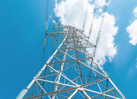
Choosing between a single circuit and double circuit configuration is an important decision in a 132 kV transmission line project. The choice affects tower structure, right-of-way requirements, transmission capacity, foundation design, construction planning, and future grid expansion.
A single circuit line carries one three-phase circuit, while a double circuit line carries two three-phase circuits on the same supporting structure. However, the right choice depends on much more than the number of circuits. Project engineers and procurement teams should also consider route conditions, expected demand, conductor arrangement, environmental loads, available corridor width, and applicable engineering standards.
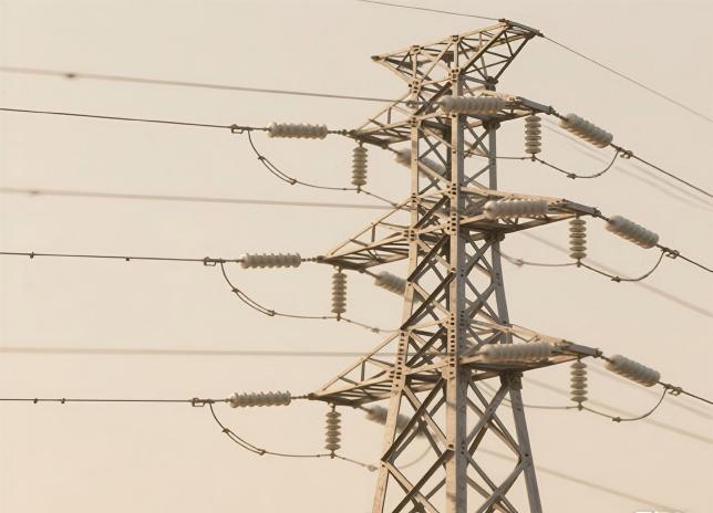
A single circuit transmission line carries one three-phase electrical circuit. The supporting tower therefore provides positions for three electrical phases, together with earth wires, insulators, fittings, and other required components.
A double circuit transmission line carries two three-phase circuits on the same tower. It therefore requires six phase positions and usually a more complex tower arrangement to maintain the necessary electrical clearances and structural strength.
| Factor | Single Circuit | Double Circuit |
|---|---|---|
| Three-phase circuits | 1 | 2 |
| Phase positions | 3 | 6 |
| Tower structure | Generally simpler | Generally larger and more complex |
| Corridor utilization | Lower capacity per tower line | Higher capacity within one corridor |
| Typical application | Projects with moderate capacity needs | Projects requiring higher or future capacity |
These are general differences rather than fixed design rules. Actual tower geometry depends on conductor size, span length, tower function, wind conditions, ice loading, terrain, electrical clearance requirements, and the design standard adopted for the project.
The main structural difference is the number and arrangement of conductors that the tower must support.
A single circuit tower generally requires fewer conductor attachment points. Depending on the project design, the three phases may be arranged horizontally, vertically, or in another compact configuration.
A double circuit 132 kV tower must support two circuits while maintaining suitable clearances between phases, circuits, the tower body, and surrounding objects. This often requires additional crossarms and may increase tower height, width, steel weight, and foundation loads.
Engineers normally consider factors such as:
Conductor and earth wire loads
Wind and ice loading
Span length
Line deviation angle
Electrical clearances
Conductor sag
Terrain and elevation changes
Tower foundation conditions
Tower function also affects the design. A suspension tower used on a relatively straight section of a 132 kV transmission line experiences different load conditions from an angle, tension, or dead-end tower.
For this reason, a transmission project normally requires several tower types rather than one standard structure for every location.
A single circuit configuration is often suitable when one circuit can meet the required transmission capacity and future expansion does not justify installing a second circuit on the same tower.
It may be appropriate when:
Current and forecast power demand can be served by one circuit
Right-of-way is readily available
A second circuit is unlikely to be required in the near future
A simpler tower and foundation arrangement is preferred
Initial infrastructure cost is an important project consideration
For example, a rural transmission route with sufficient corridor space may not require the additional structural complexity of a double circuit tower if one circuit already satisfies project capacity requirements.
However, the decision should not be based on tower cost alone. Long-term network planning, redundancy strategy, maintenance access, land availability, and future load growth should also be evaluated.
A double circuit configuration is often more suitable when a project needs greater transmission capacity within a limited corridor or when future grid expansion is already expected.
Instead of constructing two completely separate tower lines, project developers can install two circuits on one appropriately designed tower system.
A double circuit arrangement may be considered when:
Two circuits are required from the beginning
Future electricity demand is expected to increase
Right-of-way is restricted or expensive
The project needs to maximize capacity within an existing corridor
Building two separate transmission lines would create routing or land-use challenges
The trade-off is greater structural complexity. Supporting two circuits can increase tower loading, crossarm requirements, steel consumption, foundation reactions, transportation requirements, and erection complexity.
However, a double circuit system should not be evaluated only by the cost of the tower itself. In projects where land acquisition or corridor expansion is difficult, the overall project economics may still favor a double circuit design.
A useful tower specification should include more than the voltage level. Simply requesting a “132 kV transmission tower” does not provide enough information for accurate structural design or quotation.
Project teams should prepare the following information before requesting a proposal:
Circuit configuration: Single circuit or double circuit
Tower type: Suspension, angle, tension, dead-end, or special crossing tower
Conductor data: Conductor type, size, quantity, and arrangement
Earth wire or OPGW data: Type, quantity, and mechanical information
Span information: Normal span, maximum span, and special crossing requirements
Line angle: Required deviation angles for different tower positions
Environmental loads: Design wind speed, ice conditions, temperature range, and altitude where applicable
Electrical clearances: Phase spacing, conductor-to-tower clearance, and required ground clearance
Design standards: Structural, material, welding, galvanizing, and inspection requirements
Site conditions: Terrain and available geotechnical or foundation information
Providing these parameters helps the manufacturer develop a tower solution based on actual project conditions rather than a generic voltage-level design.
Junjiang provides customized electrical transmission structures for different voltage classes and project requirements. You can review more options on the Junjiang product page, including transmission towers, steel poles, and related steel structures.
Early communication between the utility, EPC contractor, line designer, and tower manufacturer can also reduce specification changes later in the project and improve coordination between tower design, fabrication, foundation engineering, and installation.
There is no universal answer to whether a single circuit or double circuit configuration is better for every 132 kV transmission line.
A single circuit line is generally suitable when one circuit meets current capacity requirements and route space is available. A double circuit arrangement becomes more attractive when higher capacity, future expansion, or limited right-of-way are important project considerations.
The final decision should consider transmission demand, route constraints, tower loading, electrical clearances, environmental conditions, foundation requirements, future network planning, and overall project cost.
If you are planning a 132 kV transmission project, you can contact Junjiang with your circuit configuration, conductor data, tower schedule, loading conditions, and applicable design standards to discuss a suitable tower solution.
A three-phase single circuit has three phase positions. Earth wires or OPGW are additional components and are not counted as phase conductors.
A double circuit three-phase line normally requires six phase positions because two independent three-phase circuits are supported by the tower.
It usually requires more conductor attachment points and greater structural capacity, but the final tower dimensions depend on loading, conductor arrangement, clearances, spans, and design standards.
Yes. Suspension towers are commonly used on straighter sections, while tension, angle, and dead-end towers are used where route geometry or longitudinal loads require them.
Typical information includes circuit type, tower type, conductor data, span length, line angle, environmental loads, electrical clearances, design standards, and available project drawings.


 English
 Español
 français
 português
 العربية
 русский